
Basics of Microcontroller programming & Lab1
2024년 7월 1일 작성
IoT 코스는 에피타 여름캠프의 첫 수업이었다. 에피타 수업에서, IoT 실습을 진행하기 위해 필요한 선수지식을 학습했다 :D
다음은 간단히 정리한 내용이다.
1. IoT and microcontrollers
IoT
What is IoT?
Network of interconnected devices embedded with sensors and software, enabling them to collect and exchange data with each other and with central systems, often facilitating automation, remote monitoring, and control.
Applications
- Smart homes
- Smart cities
- Energe engagement
- Wearables
- Health care
etc.
Advantages of IoT
- Efficiency and cost: automation & optimization of processes
- Data insights: vast mounts of data -> decision-making, predictive analysis.
- Convenience
Challenge for IoT
- Security concerns: vulnerability to cyberattacks
- privacy and security risks to users and organizations
- Interoperability Issues: Compatibility issues btw different
- Reliability: connectivity issue, device failures, or data inaccuracies. -> malfunctions
- Environmental impact: huge power consumtion, electronic wase -> increase of environmental impact.
환경문제는 좀 더 찾아봤는데, 다음 내용을 보고 이해할 수 있었다.
기술 발전에 비추어 볼 때, IoT가 어떤 방향, 어떤 방식으로 구현될지에 대한 논의가 필요하다. 엄청난 양의 IoT 기기들이 IP 기반 네트워크에 연결될 것이며 수월한 네트워크 액세스를 보장하기 위한 방안을 마련해야 한다. 수백억 개의 물체들이 IP 네트워크에 연결되는 시스템을 구현하기 위한 안정성을 확보해야 한다. 또한 인증, 암호화, 음성, 비디오 신호를 효과적으로 전달하기 위한 멀티캐스트 기능 같은 다른 ICT 기술들도 지속적으로 함께 기술개발이 이루어져야 할 것이다. 출처: KCA 아티클
Microcontrollers
What is Microcontroller?
Microcontroller is a small computer on a single integrated circuit.
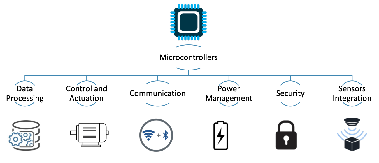
All of these items are necessary to IoT devices
-> Microcontrollers make the design of IoT devices easier by embedding all of these functions into a single
2. Prerequistes
Basics concepts of electricity
- Current : flow rate of elctrons (flux)
- measured in series, unit = Ampares (A)
- Voltage : difference in potential envergy btw two different points in a circuit
- mesaured in parallel, unit = Volts (V)
- Power : multiplication of current and voltage
- mesaured through current and voltage measurements, unit = Watts (W)
Example of an eletrical resistor: Ohms'law = characteristic of the resistor
- voltage , Resistance , then
- answer: 1A
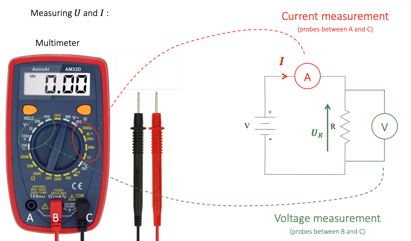
Measuring and
- by using Multimeter!
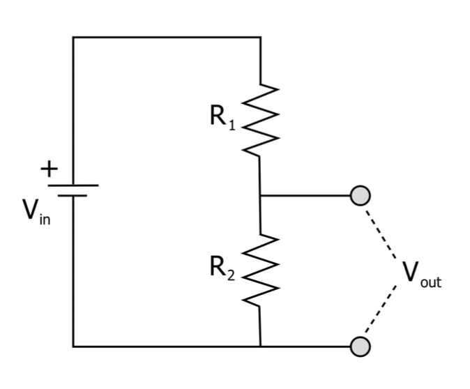
Voltage divider
transform a voltage into another voltage :D
Voltage divider can be used to
- adapt voltage ranges
- measure some displacement through a resistance variation (potentiometer) (we used potentiometer in this course)
Electrical signals: Analog & Digital
Digital signal = combination of numerical signals
simultanous or sequential transmission
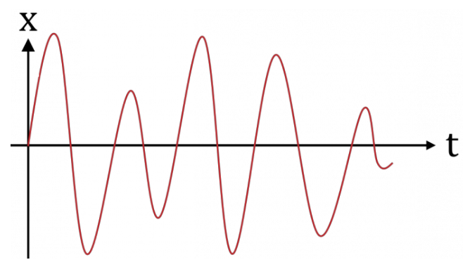
Analog signal
Example: Evolution of a temperture over time
Analog to Digital Conversion
achieved by an ADC
- Sampling
- Quantization
- Blocking
- Binary coding (with sign bit)
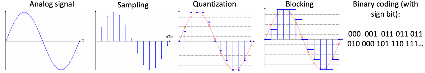
ADC is converter for analog signal to transform to Digital.
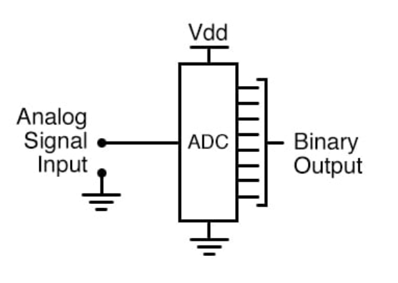
Example: 3 bit ADC with full scale voltage = 8V
ADC on different microcontrollers
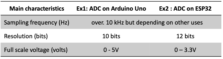
We used ESP32 in this course, then a resolution of ADC was 12 bits :D!
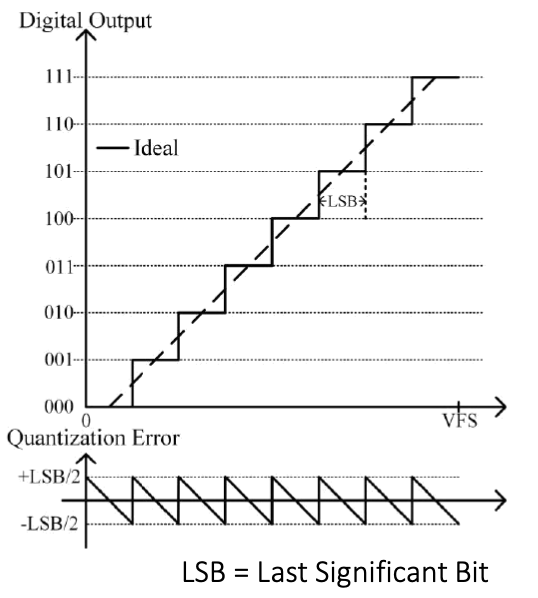
Measurement accuracy of ADC
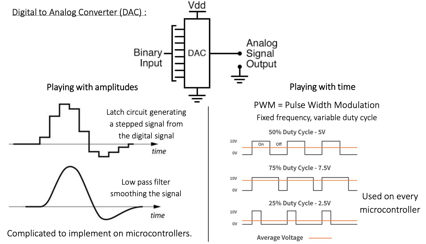
Digital to Analog Converter (DAC)
Here are two methods for implementing DAC.
- Playing with amplitudes
- Playing with time
Playing with time, especially PWM is more preferred than 'playing with amplitudes' because of its simple mechanism.
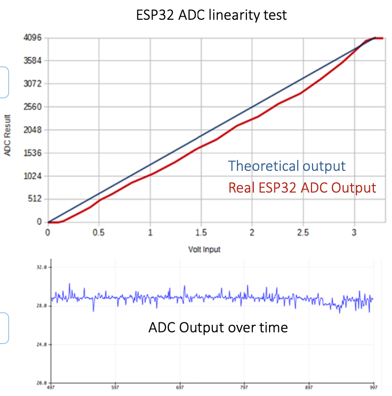
Let's see ESP32 ADC linearity test result.
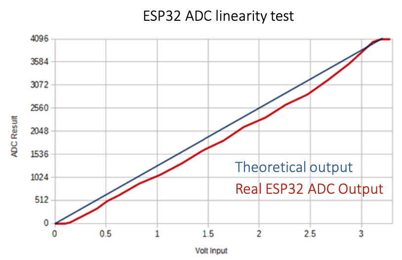
According to the result above, we can see that ADC measurement has "non-linearity". Why does real output has non-linearity?
Because ADC reads 'noise' too.
Communication interfaces
Communication interfaces are divided to two ways. One is parallel, and the other is serial.
-
Parallel Communication
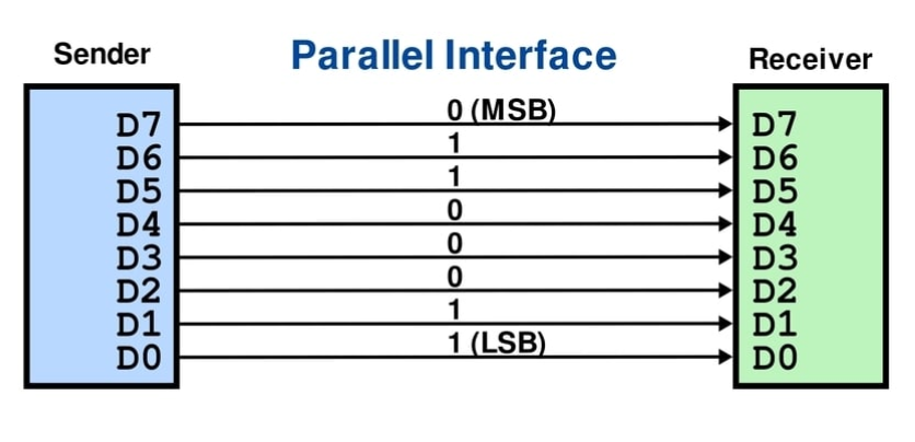
used in the past because its simplicity. Progressively replaced by serial communications with offer greater devices connection capabilities (fewer wires).
-
(Serial) Communication bus
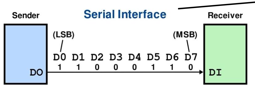
- Synchronous (synchronized by a clock signal)
- Inter-Integrated circuit
- Serial Peripheral Interface
- Asynchronous (Start and stop bits)
- Universal Asynchronous Receiver-Transmitter
- Synchronous (synchronized by a clock signal)
3. Fundamentals of microcontrollers
Microcontroller architecture
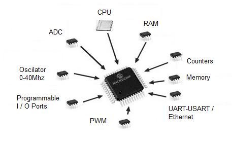
- CPU(Central Processing Unit)
- Random Access Memory
- Read Only Memory
- Input/Output ports
- Time dependent events (PWM, clock control)
- ADC (for analog inputs)
- DAC (for analog outouts)
Microcontroller Examples
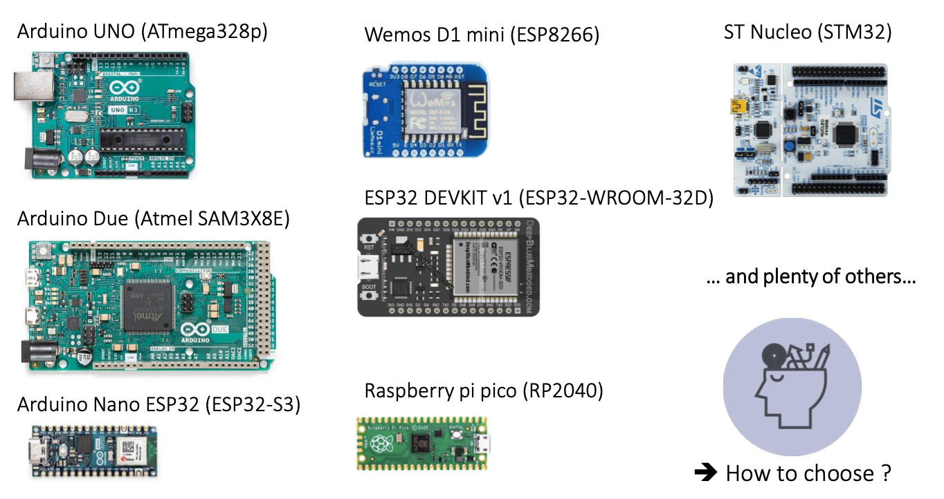
There are a lot of development boards. How can we choose a best board for this course?
Our needs for this course were ..
- Embedded programming interface (CH340 - USB)
- Integrated Wi-Fi and Bluetooth connectivity
- Available pins for connecting sensors
- Embedded camera
- Ennough power to work with images
- Capability of hosting a webserver
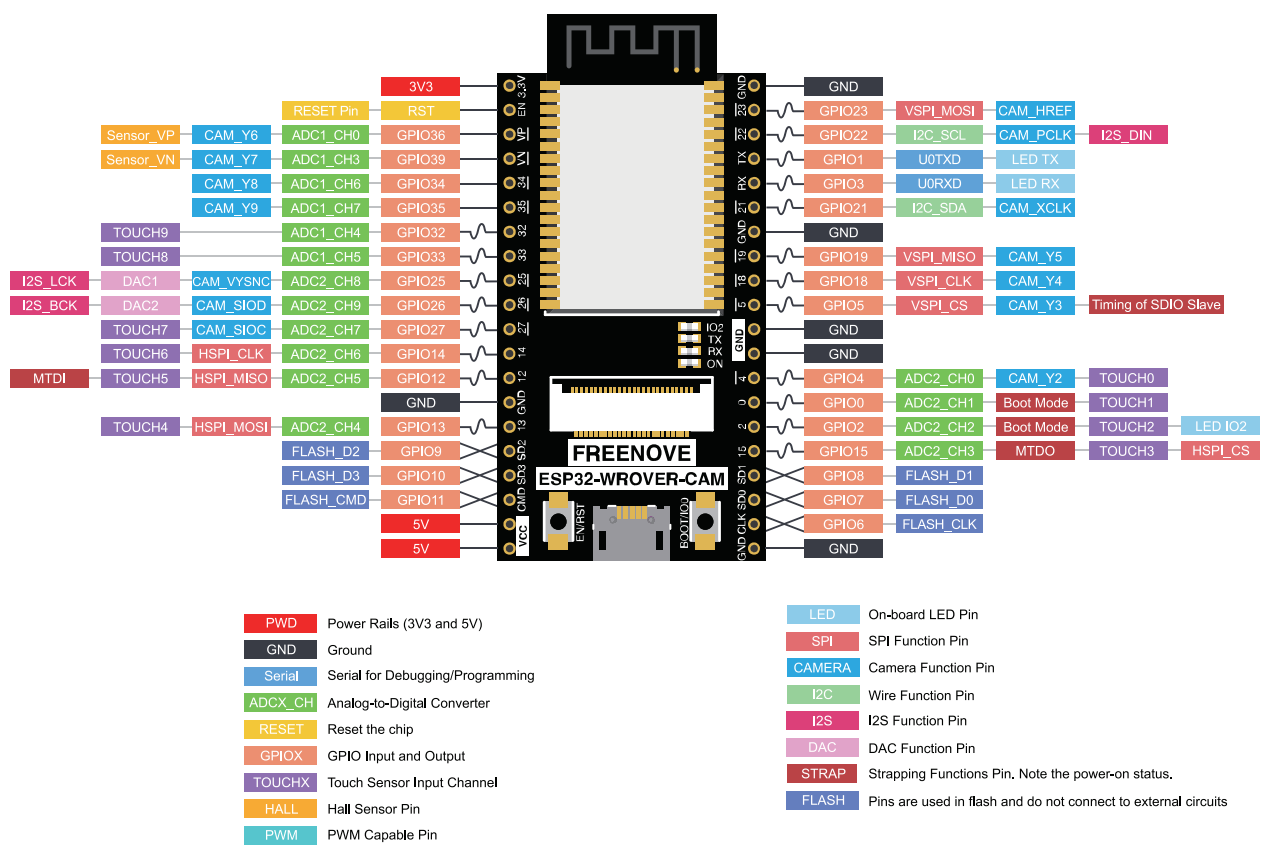
-> Choice of the Freenove ESP32 WROVER CAM board
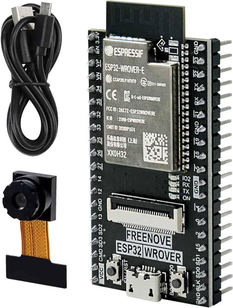
It has ESP32 Wrover Microcontroller :D
ESP32 Wrover is ESP32 with larger RAM and ROM than classical ESP32. And it is integrated PSRAM (pseudo static RAM).
ESP32 has these GPIOs.
4. Sensors
Sensor
Sensor has multiple output values(analog or digital).
Detector has one binary output (detected or not detected). And detector is often implemented as 'sensor + threshold'.
Analog sensor acquisition chain
An analog sensor acquisition chain refers to the sequence of processes and components involved in converting analog signals from sensors into a form that can be processed by digital systems. Here’s a breakdown of the typical stages in an analog sensor acquisition chain:
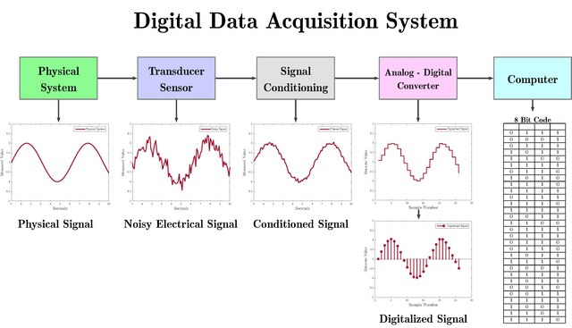
Analog sensor
Require transducer, signal conditioning, and ADC processes to convert a physical signal into a digital signal. These processes are represented by the dashed box in the diagram.
Digital sensor
Directly convert physical signals into digital signals, bypassing the need for external signal conditioning and ADC stages.
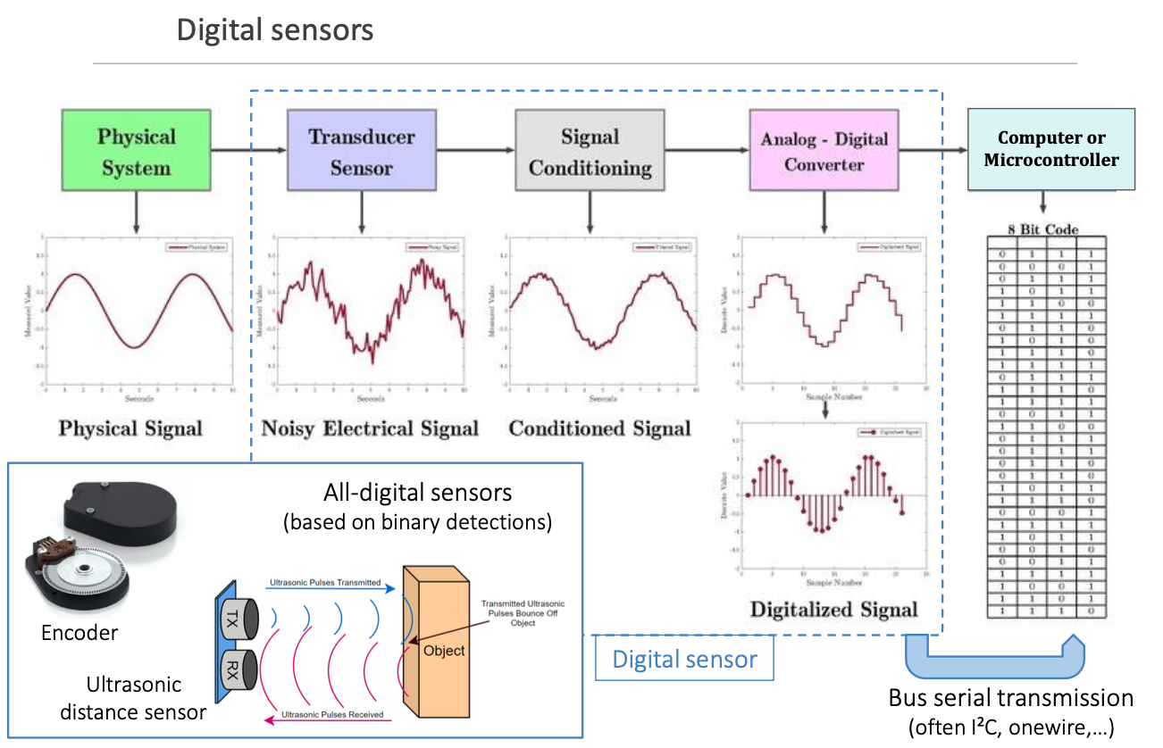
The dashed box in the diagram represents the processes involved in the analog sensor signal acquisition chain, which includes:
- Transducer Sensor: This converts the physical signal (e.g., temperature, pressure, light) into an electrical analog signal.
- Signal Conditioning: This stage processes the analog signal to improve its quality by amplifying, filtering, and level shifting it, making it suitable for the next stage.
- Analog-to-Digital Converter (ADC): This converts the conditioned analog signal into a digital signal that can be processed by digital systems like microcontrollers or computers.
Digital sensors, on the other hand, do not require the processes within the dashed box. Instead, they directly convert the physical signal into a digital signal. Digital sensors have built-in signal conditioning and ADC capabilities, so they output a digital signal that can be immediately used by digital systems. For example:
- Digital Temperature Sensor: Directly converts temperature to a digital signal.
- Digital Pressure Sensor: Directly converts pressure to a digital signal.
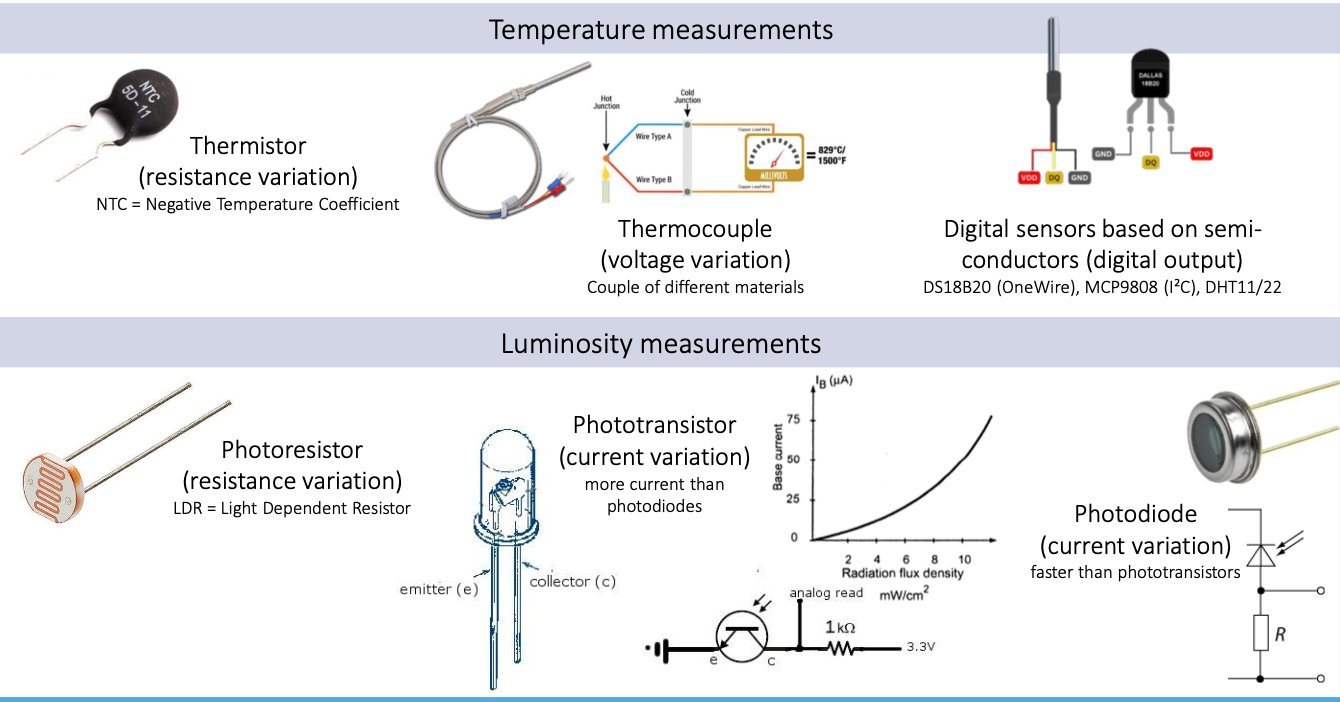
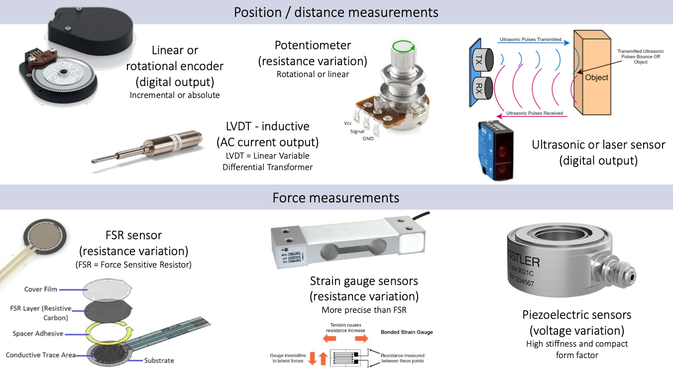
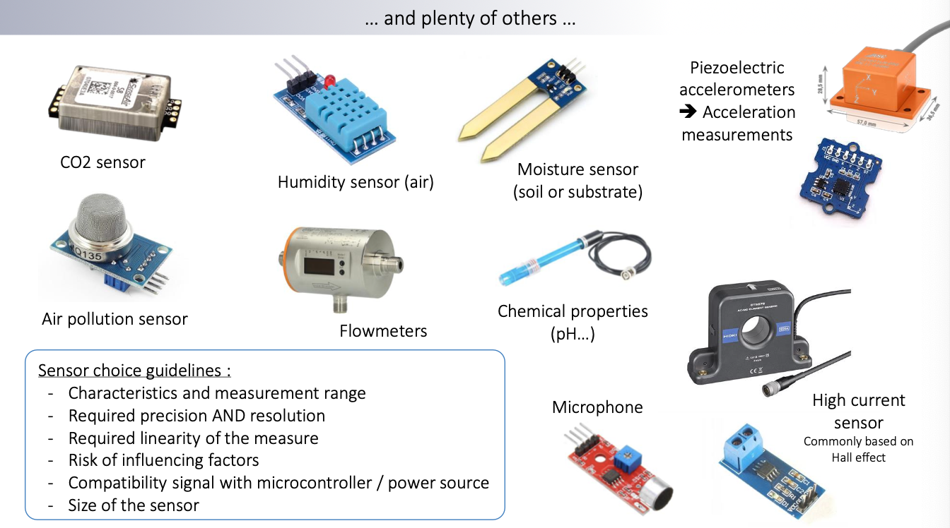
Sensor Examples
The sensors presented here are only those that are easy to connect with microcontrollers.
Exercise
Angle measurement with a potentiometer wired on an ADC pin of an ESP32 development board:
ESP32 ADC characteristics :
- Input voltage range : 0 – 3.3 V
- ADC resolution : 12 bits
- Max. current on GPIO pin : 20 mA
- Max. current draw : 250 mA
Potentiometer characteristics :
- 360° <-> 10 kΩ
-
Is the 10 kΩ potentiometer adapted to the current capabilities of the board? : board 의 최대 입력 전압은 3.3V 이다. 따라서 3.3V / 10k옴 = 0.33 mA 이므로 사용 가능하다.
-
Calculate the angular resolution of the performed angle measurement.
각도 해상도(angular resolution)의 의미
각도 해상도는 전체 각도 범위를 ADC의 단계 수로 나눈 값이다. 이 값은 포텐셔미터와 ADC 시스템이 약 0.0879°의 각도 변화를 측정할 수 있음을 의미합니다. 다시 말해, 시스템이 각도를 디지털 값으로 변환할 때 가장 작은 단위는 약 0.0879°입니다. 이 값보다 작은 각도 변화는 측정할 수 없습니다. : ADC가 0에서 3.3V 사이에서 4096 단계로 값을 나눈다고 가정할 때, 각 단계는 다음과 같다
그리고 각도해상도를 계산하면 다음과 같다.
-
How to code the angle value calculation 𝑡ℎ𝑒𝑡𝑎 from the ADC measured data 𝑠 ?
def calculate_angle(adc_value):
    # ADC 해상도와 최대 각도 설정
    adc_resolution = 4096
    max_angle = 360.0

    # ADC 값을 각도로 변환
    angle = (adc_value / adc_resolution) * max_angle
    return angle

# 예시: ADC 값이 2048일 때 각도 계산
adc_value = 2048
angle = calculate_angle(adc_value)
print(f"Calculated angle: {angle} degrees")